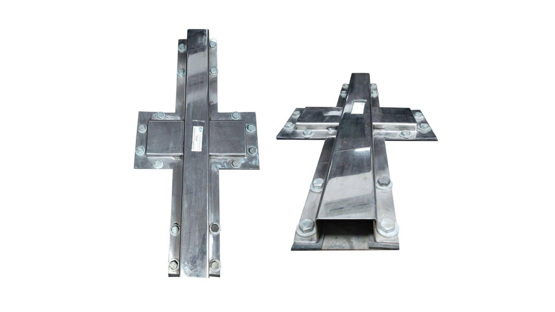
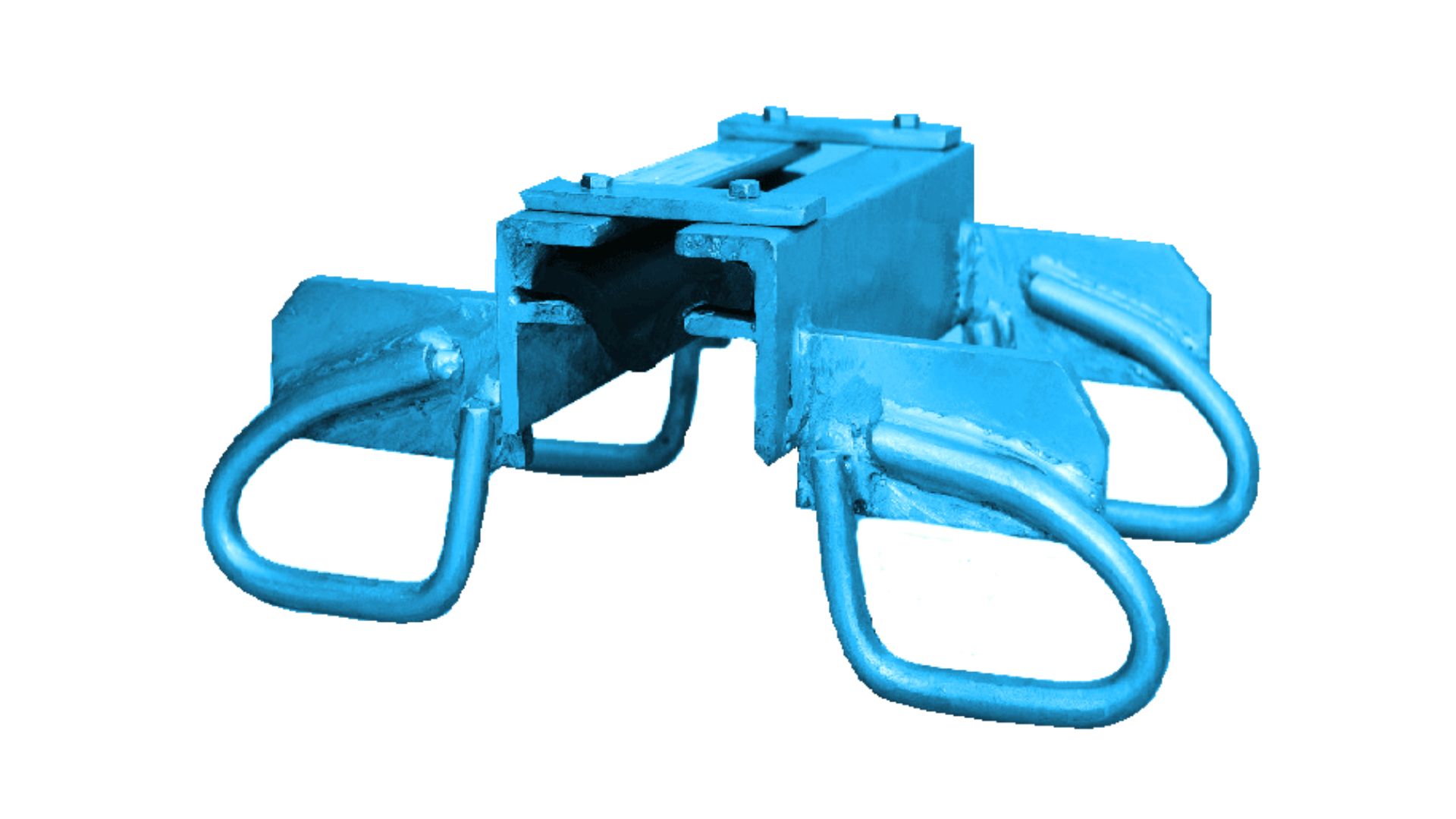
Downloads

Induction Furnance

  • An induction furnace consists of a nonconductive crucible holding the charge of metal to be melted, surrounded by a coil of copper wire.
  • 2 nos. of Induction furnaces of USA make of INDUCTOTHERM capacity of Two Tons each are installed in JKPC.

Forging

  • Forging is a process of deforming the metals and alloys into desired and specific shapes by the application of repeated blows from a hammer. Forging can be done either while the metal or the alloy is hot condition or sometimes forging can be done when the metals are in cold condition.
  • 2 nos. of Forging Hammers made up of Manchester of England capacity of Three Tons & One Tons respectively is installed in JKPC.

Heat Treatment

  • Heat treatment is a heating and then cooling process using predefined methods to achieve desired mechanical properties like hardness, ductility, toughness, strength, etc. It is the combination of thermal, industrial, and metalworking processes to alter the mechanical properties and chemical properties of metals.

CNC

  • CNC Machine is a machine with computer system which usually commands by the coded program to the physical machine for performing some cutting or shaping processes. CNC stands for Computer Numerical Control. CNC is now one of the most used technologies in the manufacturing area. JKPC have all new and sophisticated CNC Machine

Workshop

  • JKPC have a team of dedicated & well trained engineers, who work hard to handle & execute the work not only in schedule time but insure the craftsmanship of the manufactured items.

Best Laboratory

  • JKPC is having its own full fledge laboratory to insure the best quality in market.

PRINCIPLES OF PRESTRESSING

Prestressing is a method of inducing known permanent stresses in a structure or member before the full or live load is applied. These stresses are induced by tensioning the High Tensile Strands, wires or rods, and then anchored to the member being Prestressed by mechanical means.

The Prestressing counteracts the stresses, produced by subsequent loading on the structures, thereby extending the range of stresses to which a structural member can safely be subjected. This also improves the behavior of the material of which the member or structure is composed. For Example; The Concrete which has relatively a low Tensile strength, shall behave like a member having high tensile strength, after Prestressing.

The High Tensile wires/strands, when bunched together are called Cables. These cables are generally placed inside a cylindrical duct made out of either metallic or HDPE material. The Anchorages, one of the main components of the Prestressing activity, are used to anchor the H.T. Cable after inducing the Load. The whole assembly of the Anchorage and the H.T. Cable is named as ‘TENDON’.

APPLICATION AND USE OF PRESTRESSING

In structural Member, where the span length is very high with low rises and low structural height, the application of Reinforced Cement Concrete shall be virtually impractical. In such a case, Prestressing is used to achieve a light weight, elegant looking and much economical structure with high durability. Prestressing, therefore, is widely used for long span beams and Bridges.

In building structure also, prestressing method is very effectively used to achieve lighter beams and slabs; thus reducing their dead load considerably as compared to R.C.C. Structures. Application of Prestressing in building construction also facilitates a larger span between the columns, thus reduces the number of columns. This also makes the structure more versatile for interior planning

Prestressing is also very widely used in the construction of Mega Structures like Containment Wall of Nuclear Reactors, LNG Storage Tanks, Cement Silos, Chimneys, Dams and Rock Anchors etc.

TYPES OF PRESTRESSING

Prestressing System can be classified by two basic methods, as under:-

  • a. Pre-Tensioning
  • b. Post-Tensioning

Pre-Tensioning: is a method where Prestressing Steels are pre-stressed, prior to concreting, against two rigid abutments. This method is most widely used for mass production of short span structures, where pre-stressing is also a prerequisite, such as; Railway Sleepers, Electric Polls, Fencing Polls, Pre-Tensioned Slabs and I-Section Bridge Girders etc.

In this system, a number of identical structural frames are placed in between the two rigid abutments or reaction bolster. Prestressing Steel is then placed longitudinally across these frames and abutments, in the required orientation, and stressed. After achieving required elongation and stresses they are blocked at two abutments and then concrete is poured in the frames with stressed steels in position.

Post-Tensioning - is a method where Prestressing Steels are stressed after concrete attains its preliminary strength. Two extreme ends of the structure are considered as a reaction face, against which force is applied. Ducts are placed inside the formwork along with reinforcement and the concreting is completed. After achieving required concrete strength, a stipulated numbers of Prestressing Steel is then inserted in each duct for stressing purpose. After achieving required elongation and stresses they are blocked at two ends with the help of Anchor Plates and grip.

Presstressing Steel

Prestressing Steels are best known as the High Tensile Steel Wires, Strand or Bars and are available in various sizes and configurations to impart a range of UTS.

TYPES DIAMETER RANGE BREAKING STRENGTH SHAPE
Plain Round Wire 2.5mm. -8 mm. 9.87kN-69kN
Indented Wire 4mm. -7mm. 23kN-61kN
Strands-3Ply 3.0mm.x 3Wire 38.25kN
Strands-7Ply 9.5 mm-15.7mm 89kN - 265kN
Threaded Bar 20mm. -40 mm. 173kN - 691kN

High strength prestressing steels requires careful handling during transportation and storage.They should neither bed ragged on hard rough surface nor laid unprotected on naked soil. It should be properly wrapped and covered with tarpaulin etc.to preventing ress of moisture and dirt in a humid or corrosive atmosphere.

They should be stored at an elevated platform to prevent them from rising moisture if any, from the humid / wet ground condition.TheStorage area must also have an adequate ventilation, to prevent condensation.

JK Expasion Joint

When two structural elements are designed to move relative to one another, an expansion joint is usually required to seal the gap between the two elements while also accommodating their relative movements. Expansion joint in bridges are usually provided to allow for thermal expansion and contraction of the bridge deck, and to also allow for movement due to traffic actions on the bridge. The gap between the deck end and the abutment wall is frequently the case for bridges. On long viaducts or continuous bridges, however, additional joints may be required between deck portions to limit the movement at any one place.

Expansion joints are a point of weakness within a bridge due to its function, and there have been several occurrences of joints leakage, which can cause problems to the bridge. For example, corrosion of the bridge reinforcement has commonly occurred when de-icing salt-laden water has seeped onto bearing shelves or pier supports.

The required repairs are substantially more expensive than the joints initial capital cost, especially when traffic delays are included. It is therefore important to pay careful attention to the design, detailing and installation of bridge expansion joints in order to reduce the risk of future high repair costs for the bridge owner.

One of the main reasons for the rising of integral bridge design is the susceptibility of expansion joints. Integral bridge construction eliminates the requirement for expansion joints by attaching the deck directly to the abutments. The removal of expansion joints is often recommended where possible due to the problems they can cause.

An integral bridge, on the other hand, will have the same load effects and causes of movement as an expansion joint, however the effects of the movement will need to be considered in its design. However, Integral construction will not be a possibility for many bridge, especially those already built, and expansion joints will always be required.

Performance Criteria of Expansion Joints in Bridges

For an expansion joint to function well, it must possess a number of qualities. Some of them are listed below:

  1. For an expansion joint to function well, it must possess a number of qualities. Some of them are listed below:
  2. It should be watertight.
  3. It should provide a smooth ride and pose no danger to road user such as cyclists, pedestrians or equestrians.
  4. The joints skid resistance should equal that of nearby surfacing.
  5. Noise emissions from the expansion joint should be kept to a minimum, especially if it’s going to be used in residential areas.
  6. The joint should be easy to inspect and maintain.

Installation and maintenance

Installation and inferior materials are two of the most common causes of expansion joint failure. When installing expansion joints, take care and follow the manufacturer’s in instructions. Trained workers should be used, with special attention paid to identified weak spots such the interaction with the bridge deck waterproofing.

Bridge expansion joints should be inserted as late as feasible in the construction process to allow for shrinkage, creep, and settlement movements to occur before the expansion joint gap is filled.

Expansion joints should be built such all wearable pieces can be replaced or reset quickly, ideally during off-peak hours. Joint should be inspected regularly to ensure that they are still functioning correctly and have not blocked up or leaked. Because of the dangers of allowing water to spill onto other bridge parts, any blocked drainage should be cleaned as soon possible. To avoid the transmission of excessive stresses across the joint and sitting up of joints must be cleaned.

De-Watering System

The common header main pipe of the riser pipe is then connected to the well point dewatering system. Well Points are very versatile and it can be used for a wide range of applications like shallow foundation and trench works.

Well Point may be installed in parallel for particularly long pipeline trenches with the help of special trenching machines. Well Point can be used for irrigation purpose of small to medium size fields like residential gardens.

Application of Well Point System

At the following construction or project sites well point system can be adopted,

  • Hydro projects
  • Water supply projects
  • Land reclamation projects
  • Canal construction
  • Structures for thermal power plant with not too deep foundations
  • Underground tank construction
  • Bridge construction
  • Excavation of foundations for building
  • Basement construction
  • Laying of deep sewer lines
  • Tunnel work
  • Construction of subways

Advantages of Well point System

  1. Followings are the unique benefits of well point system due to which this method is commonly more preferable over other dewatering methods.
  2. Groundwater Management: The main purpose of any dewatering practice is to draw down the water table below the working platform and maintain the depressed level for the duration of the dewatering period.
  3. Area of Application: Well point system is usually most efficient to cover more land area than other as this system cover more area with a constant capacity of 100 m3/h of water, air or water, and air mixture is discharged against a head of 20 meters.
  4. strong>Design Criteria: Well point system gives you a different method to adopt and selection of the most efficient method for your particular job or site
  5. Technical Background: Dewatering is commonly required on-site when excavations are to extend beyond the subsoil water table. For shallow excavations (up to 4m) wellpoint dewatering is often the most effective method to achieve an adequate drawdown in permeable soils. (i.e. sand, clayey sand, etc.)
  6. Quick Deploy: Well-point systems can be placed on the project site very efficiently and effectively to reduce the downtime of the construction project.
  7. Less Cost: The system of wellpoint method and dewatering equipment can be taken on lease for short and long periods, and individually, to serve the builder’s dewatering requirements.
  8. More Effective: At construction projects where deep well dewatering is not required, a wellpoint dewatering system is an effective and economical way to reduce the level of the water table to the required excavation level.

Well Point

A Well Point is a piece of pipe that has openings large enough to allow water to enter but also small enough to keep the water-bearing formation in place. The well point is then drove into the ground, passing the soil and clay until it has reached water bearing gravel and sand.